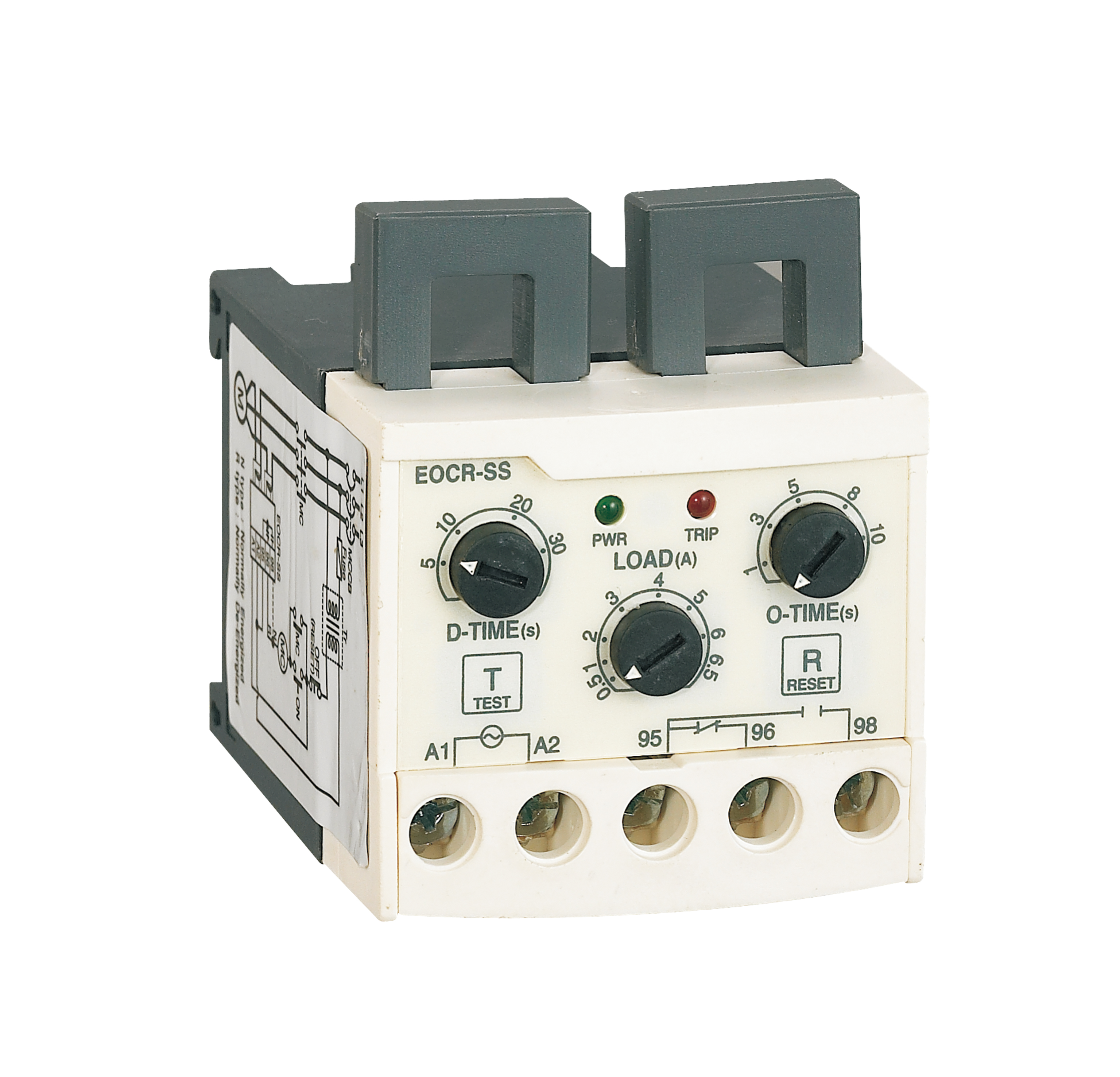
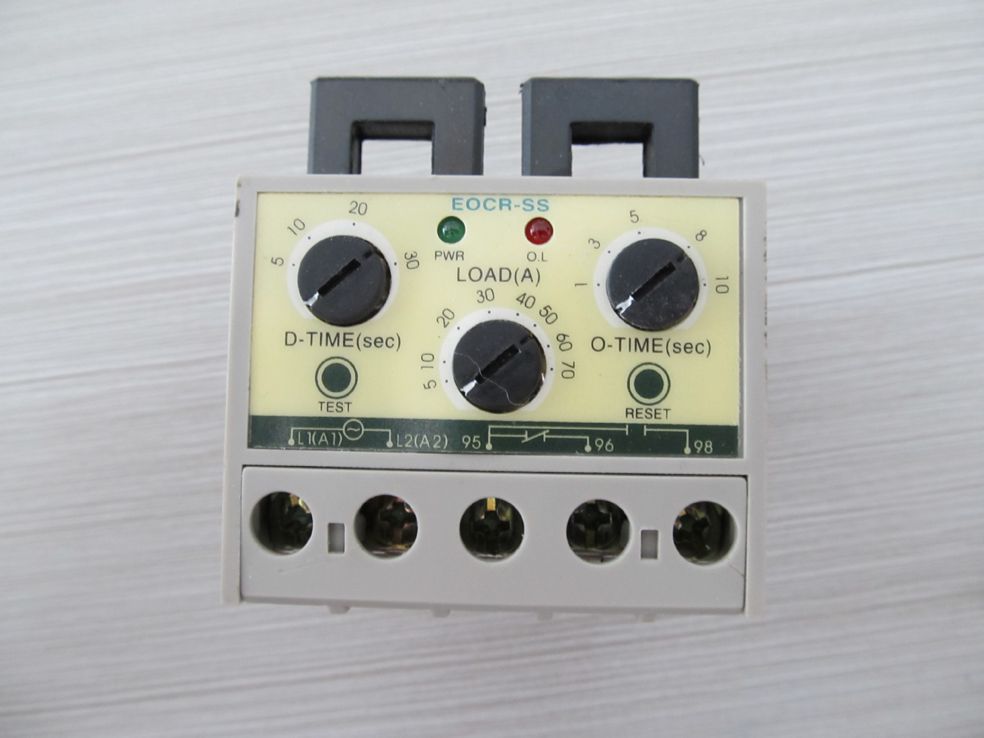
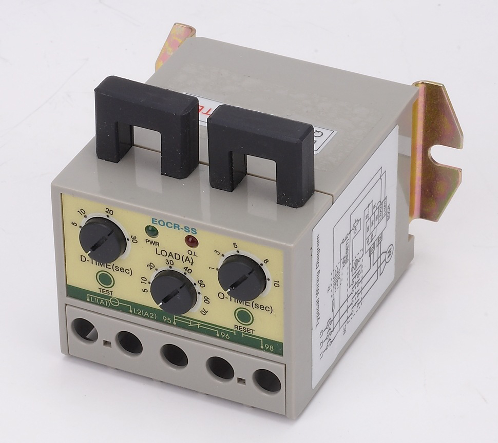
Motor protector EOCR-SS

The EOCR-SS is an overcurrent relay with ultra-small timing limit operating characteristics. The current sense signal is obtained by using the main loop phase line through two transformers (CT). When the load is abnormal, the control loop power is cut off by the internal relay to achieve the purpose of protecting the load. It has the advantages of small size, light weight, anti-interference, no noise, reliable performance, strong protection function, convenient installation and use. It is mainly suitable for overload protection of motors and equipment.
1. Function introduction:
1-1. With over current, phase loss, blocking and other protection functions.
1-2. Protection can be achieved in the range of 0.1 to 60 A using three different models (05, 30, 60). If it exceeds 60A (maximum 800A), it needs to be combined with external transformers.
1-3. Start delay, action delay, and overload value can be set separately.
1-4. The working power supply is 180~480VAC (24V, 36V, 110V, 660V power supply order production).
1-5. Two indicator lights (LED) show the power status (green) and the action status (red).
1-6. After the relay is activated, it can be reset by manual reset (press the RESET button) and power off mode.
1-7. This product has two different current models 0.5-6A 5-70A

2, the setting method
After completing the wiring with reference to the typical wiring diagram, the relay should be set up to ensure that the relay can work normally as follows:
2-1. Before the motor starts, according to the actual starting time of the motor, adjust the start delay (D-TIME) knob to this value (preferably add 2 to 3 seconds). If it is not sure, adjust the knob to the maximum value.
2-2. Adjust the action delay knob (O-TIME) and the overcurrent setting knob (LOAD) to the maximum value.
2-3. Start the motor. After the motor runs smoothly (that is, the D-TIME value exceeds the start delay time), the overcurrent setting rotation (LOAD) is slowly rotated counterclockwise until the red indicator light (LED) is on. This is the actual operation. 100% of the current value. Rotate the knob clockwise until the red indicator light has just turned off (in the set time of the action delay O-TIME), which is 103% of the actual running current value. Continue to rotate the over current setting knob (LOAD) clockwise to set it to the appropriate overcurrent value. (Recommended overcurrent value is between 110% and 125% of the actual operating current value)
2-4. Recalibrate the start delay time (D-TIME) according to the normal starting operation of the motor. The general set value is 2 to 3 seconds larger than the actual value.
2-5. Reset the action delay (O-TIME) time according to the actual situation.
2-6. After setting, press the test button (TEST) to check the setting result.
3. Indicator status description
3-1. After the relay is powered on, the green indicator light (LED) lights up, indicating that it has entered the normal state.
3-2. If the red indicator light is on during operation, it indicates that the protection function of this relay is active.
Four. Test button instructions
The relay should be tested regularly during the work as follows: Under no-load condition, press the test button (TEST) and do not let go.
The red indicator light is on. After the start delay and the action delay time, you can hear the sound of the relay of “clatter”. At this time, release the test button (TEST), the red indicator light is always on, indicating that the relay is working normally. After completing the above work, press the RESET button to reset and enter the normal working state.

★Protection project
|
Protection project |
Action (trip) time |
|
|
EOCR-SS1 |
EOCR-SS2 |
|
|
Overcurrent |
O-TIME(curve)l |
O-TIME |
|
Missing phase |
4 SEC |
4 SEC |
|
Stall |
D-TIME+O-TIME |
D-TIME+O-TIME |
|
Time characteristic |
Inverse time limit |
Inverse time limit |
★Technical Parameters
|
Current setting |
specification |
EOCR-SS1 |
EOCR-SS2 |
||
|
05 |
1~5A |
1~5A |
|||
|
30 |
5~30A |
5~30A |
|||
|
60 |
5.0~60A |
||||
|
100~(exceed60A) |
External CT work |
||||
|
time setting |
start up |
D-TIME |
0~50 SEC |
1~50 SEC |
|
|
Trip |
O-TIME |
1~10 SEC |
0.2~10 SEC |
||
|
Control voltage(50/60HZ) |
110 |
85~150VAC |
|||
|
220 |
180~260VAC |
||||
|
Relay output |
Label X1 shape and rated load |
1-SPST,3A/250VAC Resistive load |
|||
|
status |
Normally motivated |
||||
|
Label X2 shape and rated load |
1-SPDT,3A/250VAC Resistive load |
||||
|
status |
Normal without incentive |
||||
|
Time-current characteristic |
Inverse time limit |
Definite time limit |
|||
|
Trip indication |
2-LED |
||||
|
Installation method |
35mm guide |
||||


